A project has two kinds of drawing, and they do different jobs:
- Floor plans are the layouts on offer, such as “1+1” or “2+1 A”, each with its rooms, its area and a picture for buyers. A unit that has a floor plan takes its rooms and area from it.
- Traced plans and facades are the architect’s drawings of a real floor, and a render or photo of the real building, with each unit or floor outlined by hand. They make the board, the marketplace page and your website widget show the actual building, so a buyer can click the flat they want.
You need floor plans for almost every project. Tracing is optional: without it, the board still draws every building as floors and units.
Floor plans
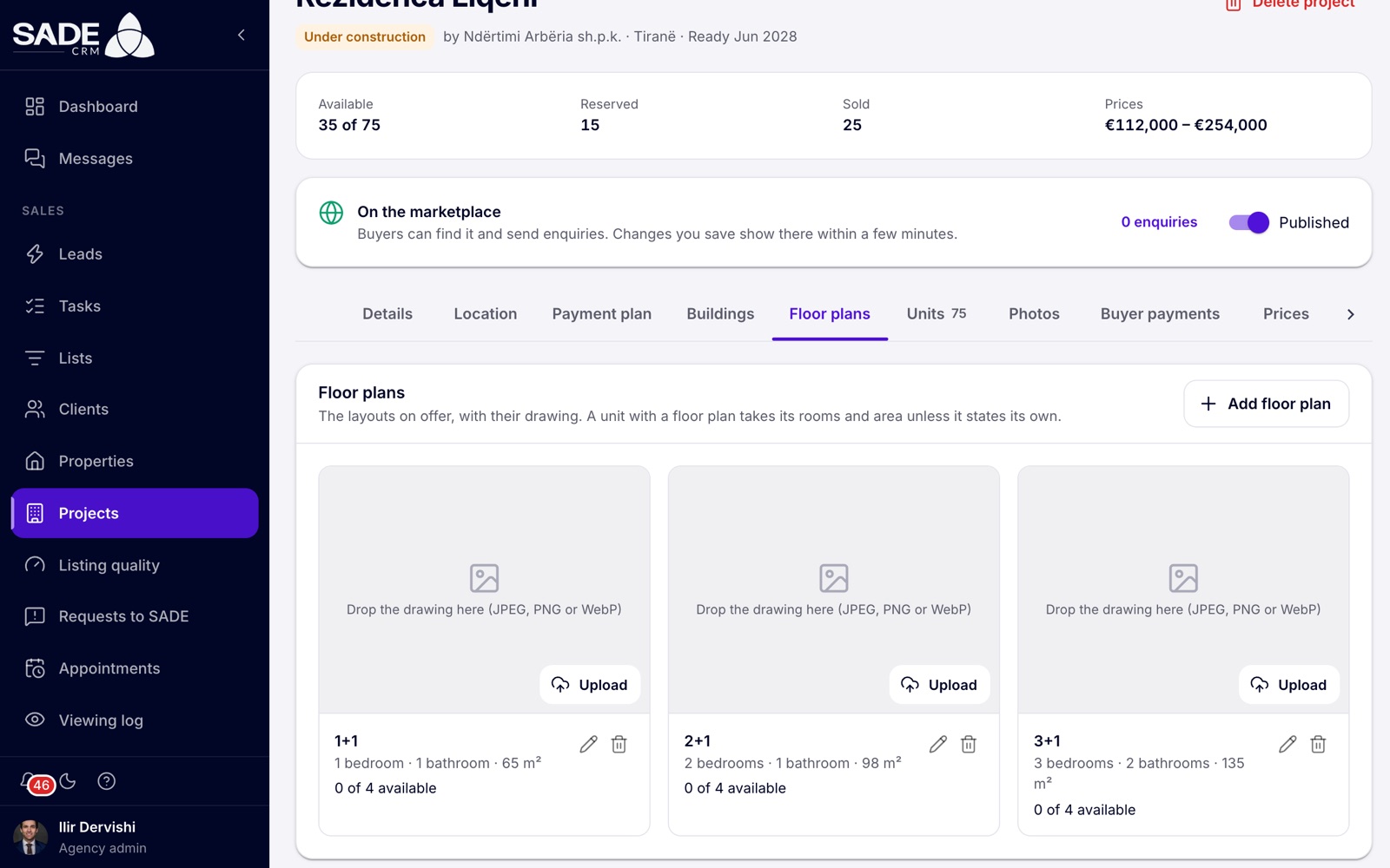
Three floor plans, each waiting for its drawing.
Add a floor plan
-
Open the project’s Floor plans tab and click Add floor plan.
-
Fill in the fields:
Field What to enter Name The layout’s name as buyers know it, such as “2+1 A”. Up to 100 characters. Bedrooms 0 to 50. Bathrooms 0 to 50. Area In m². -
Save it. The card appears on the tab.
-
Drop the drawing on the card, or click Upload. JPEG, PNG or WebP, up to 25 MB. Use Replace or Delete drawing to change it later.
Each card shows how many units of that layout are available, for example “3 of 8 available”, and “from” the price of the cheapest available one.
Edit or delete a floor plan
When you change a floor plan’s rooms or area, the units that took them from the plan follow the change. Units with their own rooms or area keep them.
Deleting a floor plan deletes its drawing. Its units keep their rooms and area, without a floor plan.
Note: the floor plan drawings are pictures for buyers. Tracing uses a separate upload, described below.
Trace a floor plan
A traced plan is a drawing of a floor with each unit’s outline clicked around it. One plan can cover many floors that are the same, a typical floor, so you trace it once. A plan for a single floor overrides the typical one on that floor.
Tracing is for admins, on the web, on a desktop-width screen.
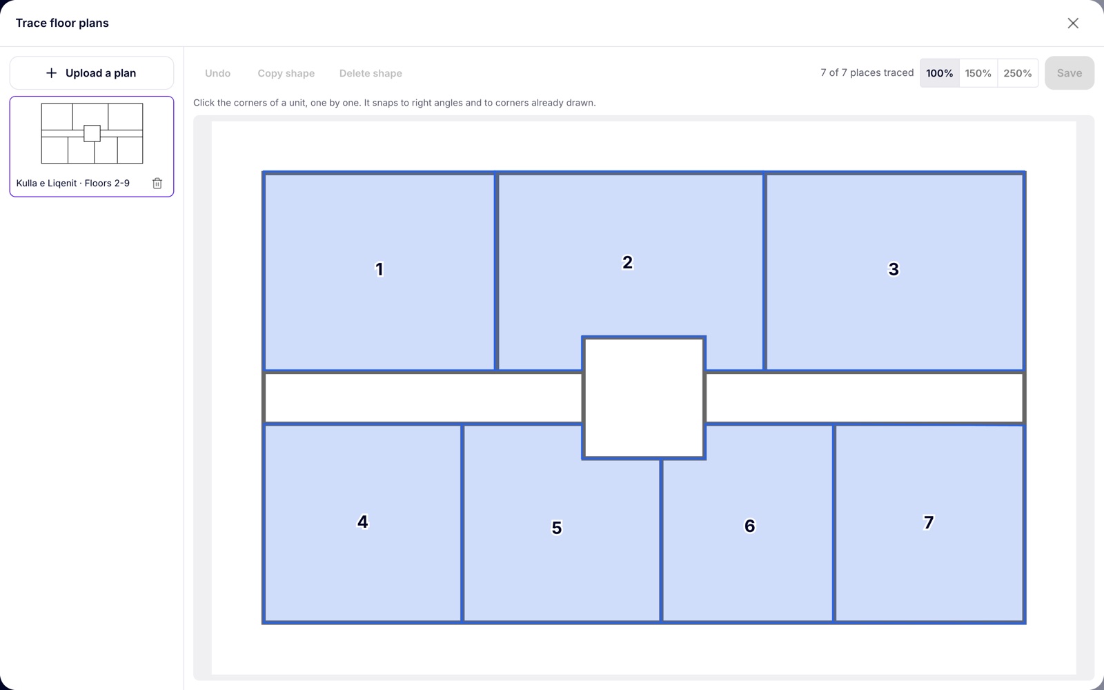
A typical floor with all seven places traced. Each shape carries the place it belongs to.
- Open Units, keep the Building view, and click Trace floor plans.
- Click Upload a plan and choose an image or a PDF of the floor.
- In the dialog:
- for a PDF, choose the Page;
- choose the Building;
- type the Floors it covers, for example “2-9”, or “12” for a single floor;
- click Add plan.
- The plan opens. The line at the top counts the places still to trace, for example “0 of 4 places traced”. The places come from the units on the floors the plan covers.
- Click the corners of a unit, one by one. The line snaps to right angles and to corners already drawn. To close the shape, click the first point again or press Enter.
- The new shape takes the next place not yet traced. To give it another one, choose it under Place on the floor.
- Trace the rest of the units the same way. For units with the same shape, select one, click Copy shape, then click where the copy goes.
- Click Save. You see “Plan saved”.
Tools
| To | Do this |
|---|---|
| Undo the last point or change | Click Undo, or press Ctrl+Z (Cmd+Z on a Mac). |
| Drop the shape you are drawing, or a copy | Press Esc. |
| Delete a shape | Select it and click Delete shape, or press Delete or Backspace. |
| Adjust a shape | Select it and drag its corners. |
| Zoom | Choose 100%, 150% or 250%. |
Rules for traced plans
- A plan is an image (or one page of a PDF), up to 25 MB.
- A floor can be in only one typical plan and in only one single-floor plan. Otherwise you see “A floor already has a plan.” A single-floor plan inside a typical one is allowed, and wins on that floor.
- A plan holds up to 200 shapes. Each shape needs at least three points and a place, and two shapes can’t share a place. Save stays greyed out until every shape has its own place.
- To remove a plan, click Delete plan. Its traced shapes go with it.
Trace the building’s facade
The facade is a render or photo of the building with each floor outlined on it. On the board, the marketplace and the widget, a buyer clicks a floor on the facade to see that floor’s plan. One image can show several buildings.
- Open Units, keep the Building view, and click Trace the building.
- Click Upload a render or photo. It takes an image, or a PDF, whose first page is used.
- The floors are listed for every building, top floor first, with a count such as “0 of 18 floors traced”.
- Click the corners of a floor, one by one, then go on to the next. On a facade the clicks snap to corners only, without squaring, because a building in perspective has no right angles.
- If a shape belongs to another floor, choose it under Floor.
- Click Save. You see “Building saved”.
Each image holds up to 200 traced floors, and each floor can be traced only once on it. A project can have several images; the phone app shows the first. To remove one, click Delete image. Its traced floors go with it.
How units find their place
A traced shape belongs to a place on the floor, such as “3” or “C”, not to one unit. On a typical floor covering floors 2 to 9, the shape for place 3 is unit A-203 on floor 2, A-303 on floor 3, and so on. SADE works out each unit’s place from its code, in this order:
- The unit’s own Place on the floor, if someone has set it.
- Otherwise, a letter at the end of the code, after a digit: “A-7C” is place C.
- Otherwise, the last number in the code, with the floor number taken off the front: A-703 on floor 7 is place 3, and A-1004 on floor 10 is place 4. On the ground floor (0) and below, the whole number is the place.
Name your codes safely
Units land in the right shape when every code ends with the floor number followed by the place, written with two digits:
| Code | Floor | Place |
|---|---|---|
| A-102 | 1 | 2 |
| A-703 | 7 | 3 |
| A-1004 | 10 | 4 |
| B-612 | 6 | 12 |
Add many → Generate floor by floor makes codes in exactly this form. See Holds and sales.
Codes that number the units through the building, without the floor first, can land on the wrong place. For example, A-12 on floor 1 reads as place 2, because the 1 at the front is taken as the floor.
Tip: if a shape lands on the wrong unit, open the unit with the pencil in the table view, set its Place on the floor to the right place, and save. The field is filled from the code, and you can change it for any one unit. It cannot be set by pasting many units.
An example
Pallati A has ten floors. Floors 2 to 9 are the same, with four flats each; floor 1 has shops, and floor 10 has four larger flats with terraces. The units were generated as A-101 to A-1004.
Ilir clicks Trace floor plans → Upload a plan and chooses the architect’s PDF. He picks Page 2, Building Pallati A, and types “2-9” in Floors it covers. The editor reads “0 of 4 places traced”. He traces the four flats clockwise; they take places 1, 2, 3 and 4 in turn, and the line reads “4 of 4 places traced”. He clicks Save.
He uploads the drawing of floor 10 with Floors it covers “10”. It has its own plan, so it doesn’t clash with the typical floor. Then he clicks Trace the building, uploads the render of both buildings, and traces Pallati A’s floors from 10 down to 1 and Pallati B’s from 8 down to 1.
On the board, Arta now clicks floor 7 on the facade, sees its plan, and clicks the outline of A-703.
Something unclear or missing? Write to [email protected] or call +355 69 808 0118.